Blog

  • Crossing the Mixed Content Boundary: abusing STUN/TURN as a Communication Channel

    TL;DR: You can send and receive data using TURN by encoding data into username and IPv6 UDP address.

    Say that you have a HTTPS website. Modern web safety forbids it from accessing insecure parts of the network using HTTP. This is usually not an issue, since signing a HTTPS certificate for a website is fairly easy thanks to Let’s Encrypt.

    However, there are situations where signing a certificate for a server is not feasible. For example, you cannot obtain a certificate for a server that is not on the public Internet.1 If I have a server running at 192.168.1.100, there are not a lot of options to communicate with it from https://example.com.2

    Examining Existing Options

    With https to http communication not being available, the remaining options are

    • Using redirects, by redirecting users from https://example.com to http://192.168.1.100 and then back to https://example.com, we can encode information in the URL, and pass them back and forth.
      • This is a lot like how SSO is implemented using SAML and OAuth2.
      • This is not great for UX. Having to redirect a user back and forth each time we want to communicate is not good.
    • WebRTC
      • WebRTC cannot by itself establish an connection. It needs a signaling server. This means that the local server would need to connect to the Internet. This may not be feasible or maybe you just don’t want to host a WebRTC signaling server.
    • Use WebRTC, but use redirects to handle signaling
      • This is a lot better than option 1, as you don’t need to do redirects every time when communication is needed.
      • However, this still requires a redirect each time the user visits the website since WebRTC sessions do not persist over navigations. So every time you go to https://example.com, the user needs to be redirected to and from http://192.168.1.100.

    Can we do better than these options? Can we establish a non-TLS connection without redirects, user interaction, or a pre-existing communication channel? Given that we have WebRTC, it means that we just need to pass about a couple KBs of data bidirectionally to establish a connection – is there any way that allows a browser to pass small amount of data crossing the mixed content boundary?

    The answer is yes, via STUN/TURN.

    Smuggling Bytes using STUN/TURN

    Both STUN and TURN are protocols of the Interactive Connectivity Establishment (ICE) suite, intended to establish connectivity though NAT.

    The purpose of STUN is to get a public UDP address of a peer. If we use IPv4, That is 6 bytes of information, 4 bytes from the IP, and 2 bytes from the port (4 bytes usable if we eliminate invalid ports and IP addresses). If we use IPv6, we can get 18 bytes of information (16 bytes usable). The problem with STUN is that there’s no user configurable input to STUN. You can receive data, but not send data.

    The sister protocol TURN is an extension to STUN. TURN allows allocating a UDP relay, in case a connection cannot be established via STUN. Since TURN is a relay server, it is a lot more expensive to run than STUN, therefore some form of authentication is usually required. TURN sends the username in plaintext. Given that the safe MTU is about 512 bytes and there’s overhead in the TURN protocol, it’s possible to send at least 256 bytes of data using a TURN username. We can receive 16 bytes of data from a TURN response, encoded in a IPv6 address and port number pair.

    We are now able to send about 256 bytes of data (encoded in username) and receive 16 bytes of data (encoded in IPv6 address and port) by abusing TURN.

    16 bytes in a response is obviously not sufficient, as a regular WebRTC SDP weighs about 1.5KB. So I developed a janky protocol that splits the request and response into smaller chunks.

    • The client first allocates a request and tells the server how big is request is going to be, encoded in the username. The server returns a 16 byte request ID.
    • The client incrementally sends the parts of the request in 256 byte chunks using the allocated request ID.
    • Once all parts are sent, the client tells the server to execute the request. The server returns the response size.
    • The client incrementally pulls the response from the server in 16 byte chunks.

    Given that a WebRTC SDP is about 1.5KB. This is going to result in about 100 TURN request and response pairs, which translates into 400 UDP packets. We transmitted 3KB using 400 UDP packets, averaging an impressive 7.5 bytes transmitted per UDP packet.

    This is not great. So I trimmed the response SDP down by removing unnecessary information (in particular, redundant candidates). This brought down the SDP size to about 700 bytes.3

    This is still not great, so I added ZLIB compression using a pre-defined dictionary. I compressed the SDPs down to about 300 bytes each – now we only need to send about 80 UDP packets.

    Now we can establish a communication channel by only using IP address + port.

    Putting it All Together

    I made a demo at https://codepen.io/gyf304/pen/oNrjoJj. The demo fetches a proxied version of https://example.com over TURN. It requires 0 user interaction (apart from clicking the “Execute” button) to communicate with a non-secure server from a secure origin.

    I also published NPM packages @turnx/server and @turnx/client, in case people want to give it a spin. The @turnx/server package provides a server that allows you to proxy a HTTP/HTTPS website over TURN, and the @turnx/client package provides a client that implements a similar interface to fetch. The packages are not documented, but the demo above should be sufficient to get you going.

    The source is available at https://github.com/gyf304/turnx.

    It is also worth noting that this communication protocol is extremely inefficient, so the intended usage is to use this to establish an actual connection using WebRTC (e.g. by using WHIP).

    Also: don’t do this over the public Internet.

    1. You can technically sign a cert for a local address using techniques outlined in https://letsencrypt.org/docs/certificates-for-localhost/. But as the article also pointed out, distributing a private cert as part of a software package is a big no-no. ↩︎
    2. Why would someone want to communicate to a LAN server from a secure HTTPS website? I can think of a few use-cases: a media app like Plex where logic is served from a HTTPS remote server, or a PWA, and the content is stored on a local server; a HTTPS website for upgrading the firmware of a LAN only appliance; or a web app to transfer files in a LAN and you don’t want to build a WebRTC signaling server. ↩︎
    3. You can reduce this further. In fact, people have encoded an SDP in 106 bytes! (https://webrtchacks.com/the-minimum-viable-sdp/) ↩︎
  • IPv4 Network Address Translation for Steam (NAT4S)

    TL;DR – I made Steam multiplayer possible with classic LAN games through a project called PartyLAN. It enables network address translation (NAT) between IPv4 and Steam IDs.

    Network address translation (NAT) is not an obscure concept – it has been in use since 1994. The basic idea is simple: a router, either software or hardware, takes packets from an incoming IP address (e.g., 192.168.1.123), converts it to another address (e.g., 1.2.3.4), and sends it out. The router also performs the reverse process, converting packets from the outside address (IP 1.2.3.4) to the inside address (e.g., 192.168.1.123).

    This concept is widely used, and there are several variants of NAT based on the address space it maps from and to:

    • NAT44 – the most common form of NAT, which converts between two IPv4 addresses, typically between a class A, B, or C private address space and the public IP address space (e.g., between 192.168.1.123 and 1.2.3.4). This is what home routers use.
    Illustration of NAT44 (made by Michel Bakni)
    • NAT444 – a variant of NAT44 that adds an intermediate CGNAT address space. (e.g. 192.168.1.123, then 100.89.199.129, finally to 1.2.3.4).
    • NAT64 – converts an IPv6 address to an IPv4 address and is commonly used to provide IPv4 connectivity to IPv6-only devices

    By applying the concept of NAT to Steam, which can be seen as a network with Steam user IDs as network addresses, it becomes technically feasible to perform network address translation between IPv4 and Steam IDs. I refer to this as NAT4S.

    How is this useful?

    For PC gamers, the standard method of playing multiplayer games is Steam Multiplayer. However, older games use the vanilla IP stack designed for LAN party-style multiplayer. Playing these games over the internet is challenging for non-technical individuals and often involves configuring the firewall on the home router. By implementing a network address translator that converts between IPv4 and Steam Networking, classic games can seamlessly communicate over Steam Networking.

    The Implementation

    I opted to use the CGNAT address space (100.64.0.0/10) for the mapping. Unlike traditional class A/B/C private addresses, this address space is rarely used by end-user devices.

    However, a problem arises immediately: the CGNAT address space only contains about 4 million addresses, which may seem like a lot but is significantly smaller than the number of Steam accounts, exceeding 1 billion. So, how do we accommodate 1 billion accounts with just 4 million addresses? The answer is simple: we don’t. On average, a Steam user has fewer than 100 friends, and Valve limits the number to 250. By taking the Steam ID modulo 4 million, the chances of collision are incredibly small (around 0.1%) for the average user. In the unlikely event of a collision, we increment the address by 1 until a free address is found. This IP allocation method ensures relatively stable IPs that are likely to be the same on different computers. It is also stateless, eliminating the need for a DHCP-like protocol.

  • Janky NTP – Setting System Time Using HTTP

    I often find myself fighting with using NTP on linux machines – usually something goes wrong: maybe ntpdate isn’t there, or for some reason UDP is blocked, or maybe for some reason it just doesn’t want to do it. Here’s my janky version of ntpdate that overcomes those issues:

    date -s "$(curl -si 1.1.1.1 | grep Date: | cut -d ' ' -f 2-)" && hwclock --systohc

    Here’s ChatGPT explaining this bash one-liner to you:

    This command is setting the system date and time based on the date and time provided by the 1.1.1.1 server and then synchronizing the system hardware clock with the new system date and time.

    Here is a breakdown of the command:

    date -s "$(curl -si 1.1.1.1 | grep Date: | cut -d ' ' -f 2-)": This sets the system date and time. The curl command is used to send an HTTP request to the 1.1.1.1 server and retrieve the server’s response. The -si option tells curl to include the HTTP headers in the output and to be silent (i.e., not to show a progress meter or error messages). The output of curl is then piped to grep Date:, which searches for the string “Date:” in the output and prints the matching lines. The output of grep is then passed to cut, which extracts the second field (i.e., the date and time) from the input and prints it. The date and time is then passed as an argument to the -s option of date, which sets the system date and time to the specified value.

    hwclock --systohc: This synchronizes the system hardware clock with the system date and time. The --systohc option tells hwclock to copy the system time to the hardware clock. The hardware clock is a battery-powered clock that keeps track of the time even when the system is turned off. This ensures that the system clock is set to the correct time when the system is next booted.

    Of course, if NTP works for you, don’t use this.

  • File System as Partition Table

    If you squint really hard – a partition table is basically a filesystem with only a handful of files – a partition table of, say, 4 partitions, is conceptually pretty much the same as a filesystem with only 4 files in it – the filesystem labels are the filenames, and the partitions are just the files.

    So why don’t we use a filesystem as a partition table and boot a OS from it? The pros of doing that is quite obvious: All partitioning operations previously done using fdisk or parted can now be done with file managers, or common UNIX utilities like cp and truncate. To add a new partition, add a new file; to remove a partition, delete the file; to make a partition larger, simply extend the file – no more moving other partition around like playing Klotski.

    This is especially true for beginners – one big hurdle to jump using a Raspberry Pi – is to prepare a SD card. Without prior knowledge of MBR or GPT, this process is quite error prone. If we’re using a filesystem as a partition table, the provisioning process is just copying some files into a FAT32 disk, which comes standard on most SD cards. Upgrading the OS is no different from copying files – which can be easily done in any OS.

    Proof-of-Concept

    Let’s get a proof of concept running – we want to prepare a SD card with a single partition, have a image file root.img in there, and boot off of it. In linux terms – mount the root.img as a loop device, and use that as root.

    Linux itself, does not have the capability of directly booting from a image file as root. We have to do it in a more roundabout way.

    1. Boot to a initramfs
    2. Mount devtmpfs, proc, and sys.
    3. Mount the filesystem containing the image file, in the case of Raspberry Pis, this is /dev/mmcblk0p1.
    4. Mount the image file using a loop device.
    5. switch_root to the actual rootfs.

    For the initramfs, we use BusyBox with a custom init file, with a few extra utilities written in shell script.

    The boot process is roughly the following:

    1. Linux starts /init in the initramfs.
    2. Wait 5 seconds, if the user interrupts, offer options to use a rescue shell, reboot or shutdown.
    3. Mount /dev/mmcblk0p1 to /boot and give control to /boot/init. We do this because initramfs is not persistent, and we want to boot process to be configurable.
    4. Wait 5 seconds, if the user interrupts, let the user select a image to boot.
    5. Mount the image (default /boot/root.img) and switch_root
    6. Raspbian takes over.

  • CRT Miniature Arcade Cabinet

    CRT Miniature Arcade Cabinet

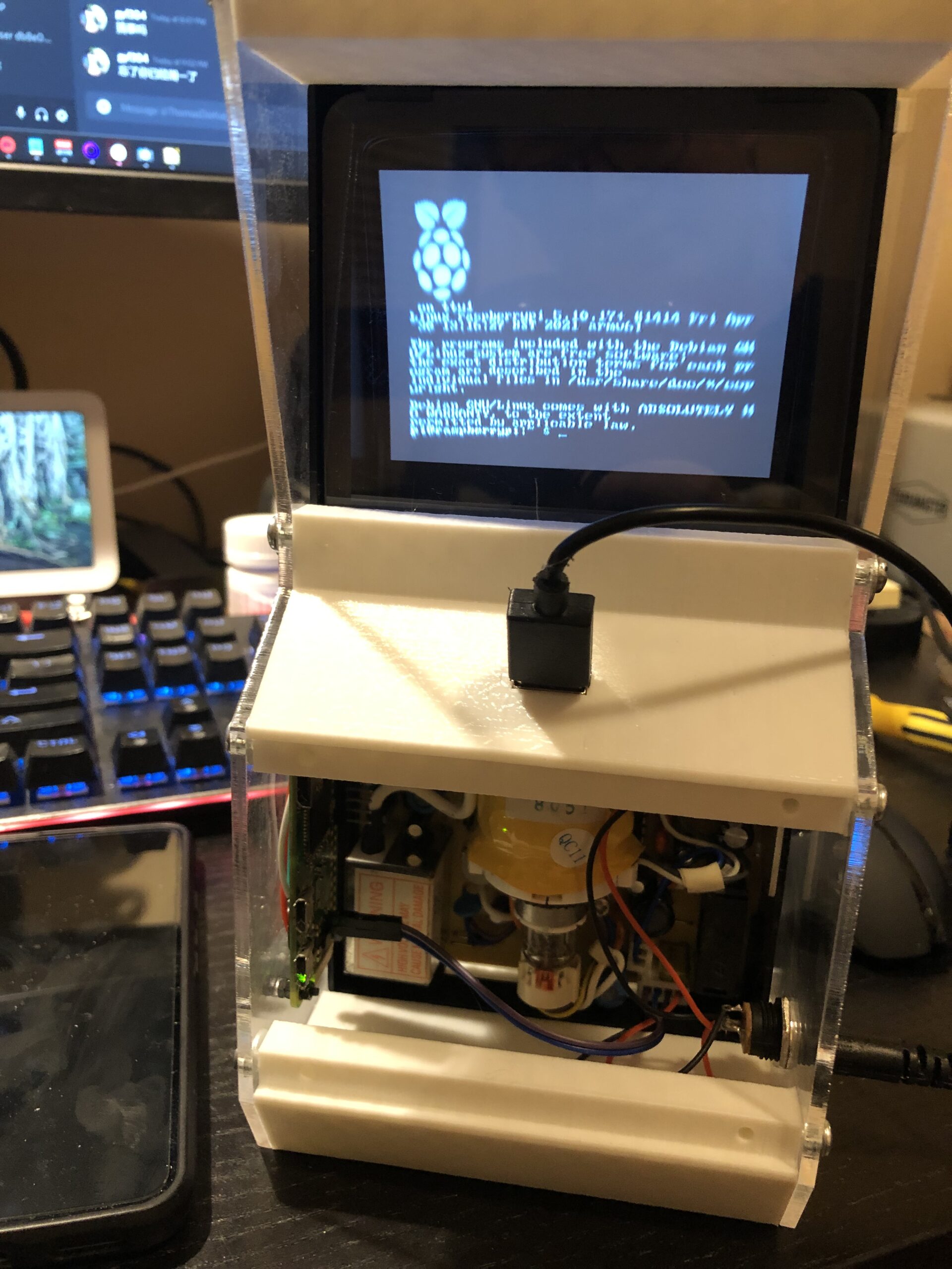
    Hey I did a thing – a raspberry pi powered miniature arcade cabinet – with an actual real 4-inch monochrome CRT.

    Next step – port WASM4 to RPi0 (or wait for someone to do that).

  • Fixing Analog Stick Input in PPSSPP

    Fixing Analog Stick Input in PPSSPP

    PPSSPP is one of my favorite emulators. First introduced to me when I was still in high school, it is my go-to (or, only?) choice if I want to revisit some old PSP games. Though I ran into an issue that I was not able to run, only walk, diagonally in Metal Gear Solid: Peace Walker, while using a controller on Android.

    After some investigation I found out the root cause: PSP analog stick input uses max-norm (shown as p=∞ below), not Euclidean-norm (shown as p=2 below), which most other controller uses.

    In a simpler sentence: When you draw a circle using a regular controller analog stick, you get a circular input; when you draw a circle using a PSP analog stick, you get a square.

    Illustration of the unit circles of some p-norms. By QuartlOwn work, CC BY-SA 3.0, Link

    Apparently, the Android controller backend in PPSSPP did not perform this circle to square conversion, thus causing this issue. This is evidenced in the GIF below, using the PPSSPP analog stick viewer.

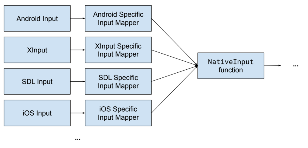
    Now, the easiest way of fixing this is to implement the circle to square mapping in the Android analog input backend, but that’s not the best solution. For historical reasons, the analog stick input is architected as the following

    PPSSPP 1.11 Design for Analog Input

    Analog stick mapping is done by each backend separately, with the XInput implementation being the more feature-complete one. The other ones usually have fewer features or are somewhat broken (e.g. lacking the necessary circle to square mapping). What we need is to refactor this into something more reasonable.

    A Better Analog Input Design

    This ensures that no matter which input backend you are using, you use the same, unified input mapper implementation. This ensures feature parity across all input backends. We just need to implement a correct, feature-complete unified input mapper.

    After a few hours, I have the refactor done, and it was eventually merged into master. The fix will most likely be available in the future 1.12 release of PPSSPP, and people can now have their game characters run diagonally.

  • Home Automation – Kubernetes Style

    Home Automation – Kubernetes Style

    I’ve been using Smartthings as my smart home hub for a while. And I’d like to migrate to something that’s open source (or more importantly, self-hosted). There’s been a few horror stories out there that make me worry about the potential “hostage” situation. (e.g. manufacturers charging a monthly price for the service, or flat-out discontinuing the service).

    Hardware

    Image 31 - Dell Wyse N03D Thin Client Celeron CPU N2807 1.58GHz 16GB SSD, 4GB DDR3 (NEW)
    Dell Wyse N03D
    Z-Wave + Zigbee Dongle

    I bought a Dell Wyse N03D Thin Client off eBay at $35 each, complete with power supply, keyboard and mouse. The thin client is definitely not a powerhouse, but it’s dual core x86-64 processor and 4GB of RAM should be plenty sufficient for my use case. To let it connect to Z-Wave and ZigBee devices, I also paired it with a dongle.

    Software

    OS

    The thin client came with Windows 7 Embedded pre-installed, which I absolutely don’t need. I replaced it with a fresh install of Ubuntu Server 20.04 LTS. As the thin client only has 16G of onboard storage, I modified the default partitioning scheme to get more space to the rootfs.

    Kubernetes

    I chose k3s for this project. It’s small size is a perfect fit. For the installation, running the following snippet is sufficient.

    curl -sfL https://get.k3s.io | sh -

    Running rancher is always a good idea. To have rancher installed on k3s, add the following manifest to /var/lib/rancher/k3s/server/manifests

    ---
    apiVersion: v1
    kind: Namespace
    metadata:
      name: cattle-system
    ---
    apiVersion: helm.cattle.io/v1
    kind: HelmChart
    metadata:
      name: rancher
      namespace: kube-system
    spec:
      chart: https://releases.rancher.com/server-charts/stable/rancher-2.5.8.tgz
      targetNamespace: cattle-system
      valuesContent: |-
        hostname: [REDACTED]
        tls: external
        replicas: 1

    This works because k3s comes with a helm CRD.

    Following that, apply the following manifest to get home-assistant and its friends installed.

    ---
    apiVersion: v1
    kind: Namespace
    metadata:
      name: home-assistant
    ---
    apiVersion: v1
    kind: Service
    metadata:
      namespace: home-assistant
      name: home-assistant
    spec:
      selector:
        app: home-assistant
      ports:
      - name: http
        protocol: TCP
        port: 80
        targetPort: 8123
    ---
    apiVersion: apps/v1
    kind: Deployment
    metadata:
      namespace: home-assistant
      name: home-assistant
      labels:
        app: home-assistant
    spec:
      replicas: 1
      selector:
        matchLabels:
          app: home-assistant
      template:
        metadata:
          labels:
            app: home-assistant
        spec:
          affinity:
            nodeAffinity:
              requiredDuringSchedulingIgnoredDuringExecution:
                nodeSelectorTerms:
                - matchExpressions:
                  - key: kubernetes.io/hostname
                    operator: In
                    values:
                    - homelab-us-east-1-nano-1
          containers:
          - name: home-assistant
            image: homeassistant/home-assistant:stable
            ports:
            - containerPort: 8123
            volumeMounts:
            - mountPath: /config
              name: config
            - mountPath: /dev/ttyUSB1
              name: zigbee
            securityContext:
              privileged: true
          volumes:
          - name: config
            hostPath:
              path: /etc/home-assistant
              type: DirectoryOrCreate
          - name: zigbee
            hostPath:
              path: /dev/ttyUSB1
    ---
    apiVersion: networking.k8s.io/v1
    kind: Ingress
    metadata:
      namespace: home-assistant
      name: home-assistant
    spec:
      rules:
      - host: [REDACTED]
        http:
          paths:
          - pathType: Prefix
            path: /
            backend:
              service:
                name: home-assistant
                port:
                  number: 80
    ---
    apiVersion: v1
    kind: Service
    metadata:
      namespace: home-assistant
      name: zwavejs2mqtt
    spec:
      selector:
        app: zwavejs2mqtt
      type: NodePort
      ports:
      - name: http
        protocol: TCP
        port: 8091
        targetPort: 8091
        nodePort: 30091
      - name: ws
        protocol: TCP
        port: 3000
        targetPort: 3000
    ---
    apiVersion: apps/v1
    kind: Deployment
    metadata:
      namespace: home-assistant
      name: zwavejs2mqtt
      labels:
        app: zwavejs2mqtt
    spec:
      replicas: 1
      selector:
        matchLabels:
          app: zwavejs2mqtt
      template:
        metadata:
          labels:
            app: zwavejs2mqtt
        spec:
          affinity:
            nodeAffinity:
              requiredDuringSchedulingIgnoredDuringExecution:
                nodeSelectorTerms:
                - matchExpressions:
                  - key: kubernetes.io/hostname
                    operator: In
                    values:
                    - homelab-us-east-1-nano-1
          containers:
          - name: zwavejs2mqtt
            image: zwavejs/zwavejs2mqtt:4.5.1
            ports:
            - containerPort: 8091
            - containerPort: 3000
            volumeMounts:
            - mountPath: /usr/src/app/store
              name: config
            - mountPath: /dev/ttyUSB0
              name: zwave
            securityContext:
              privileged: true
          volumes:
          - name: config
            hostPath:
              path: /etc/zwavejs2mqtt
              type: DirectoryOrCreate
          - name: zwave
            hostPath:
              path: /dev/ttyUSB0

    Done

    I also used Cloudflare Argo tunnel to allow me to control my home automation outside of my house.

  • Upgrading K40 Cooling System with RGB and Peltier Cooler

    Upgrading K40 Cooling System with RGB and Peltier Cooler

    The K40 laser cutter, if you know about it, comes with absolutely the bare minimum to get you started. Fortunately, it does comes with a cooling solution: You supply your own water bucket, fill it with distilled water, and drop in the supplied water pump. Failure to do that will probably result in a burnt out laser tube.

    As you can probably imagine: this is not a super good system – the system is open-air, and is therefore easy to get contaminated. In my case, my coolant reached questionable consistency (that is, gooey) after a couple of month. So I swapped out the “supply-your-own-bucket” cooling system for a “amazon-cheap-pc-water-cooling” system.

    The system is simple and consisted of 5 parts:

    • a off-the-shelf PC water-cooling pump / reservoir combo
    • a peltier cooler
    • a water-cooling heat-exchanger
    • a CPU cooler
    • a PC power supply

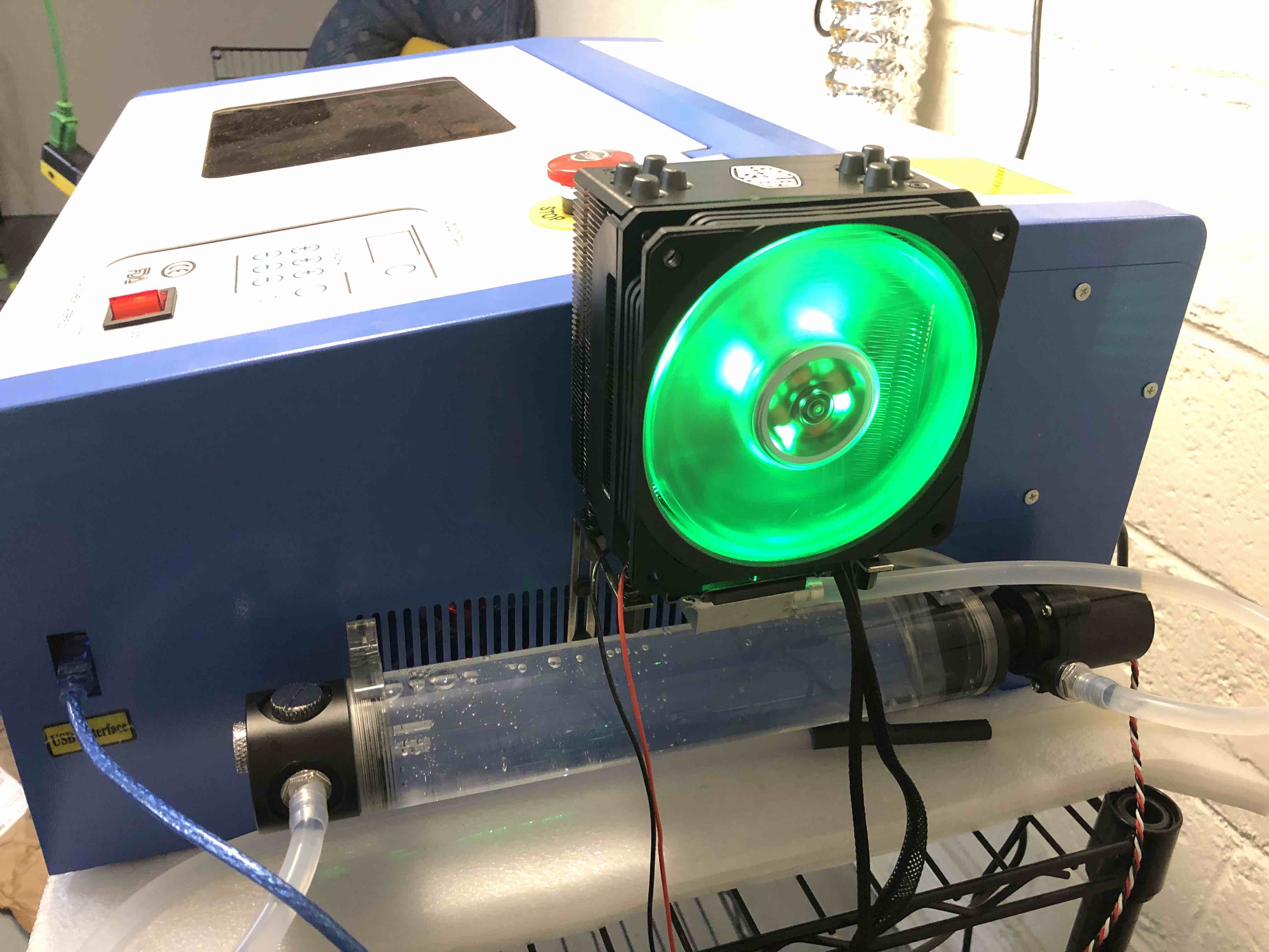
    The pump feeds water into a heat-exchanger, where heat gets extracted by the peltier cooler into the CPU cooler, then into the laser tube and back into the reservoir.

    Everything got mounted on to the side of the machine. It looks reasonably good.

    Laser Cutter with PC cooling parts. And yes, the fan is RGB.

    I hope this results in lower machine maintenance in the future.

  • Etch-A-Sketch Pro – Rotary Encoders as Mouse(s)

    Etch-A-Sketch Pro – Rotary Encoders as Mouse(s)

    I recently got a few of those rotary encoders – I was planning to make them into a follow-focus system. It’s a two part process: 1 – make a USB interface for them; 2 – make software that uses Canon’s EDSDK to interface with my camera.

    So I decided to start on 1, then I got a bit carried away and got this monstrosity made – an Etch-A-Sketch for computers, because everything deserves rotary encoders.

    Etch-A-Sketch Pro in Action

    If you look very closely, each of the encoders has it’s own plug, since each is a independent USB HID device.

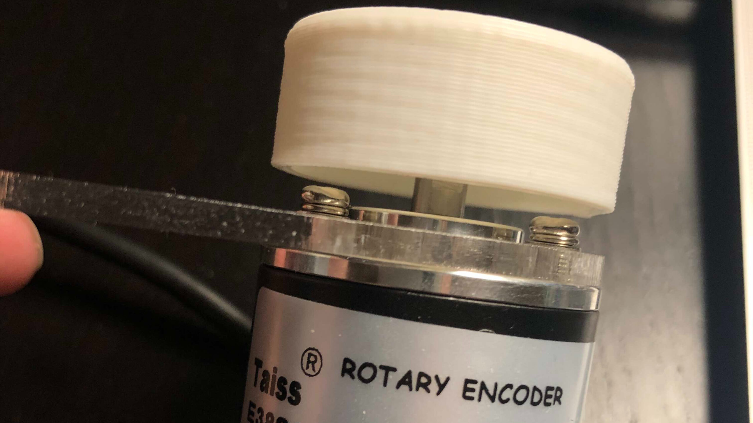
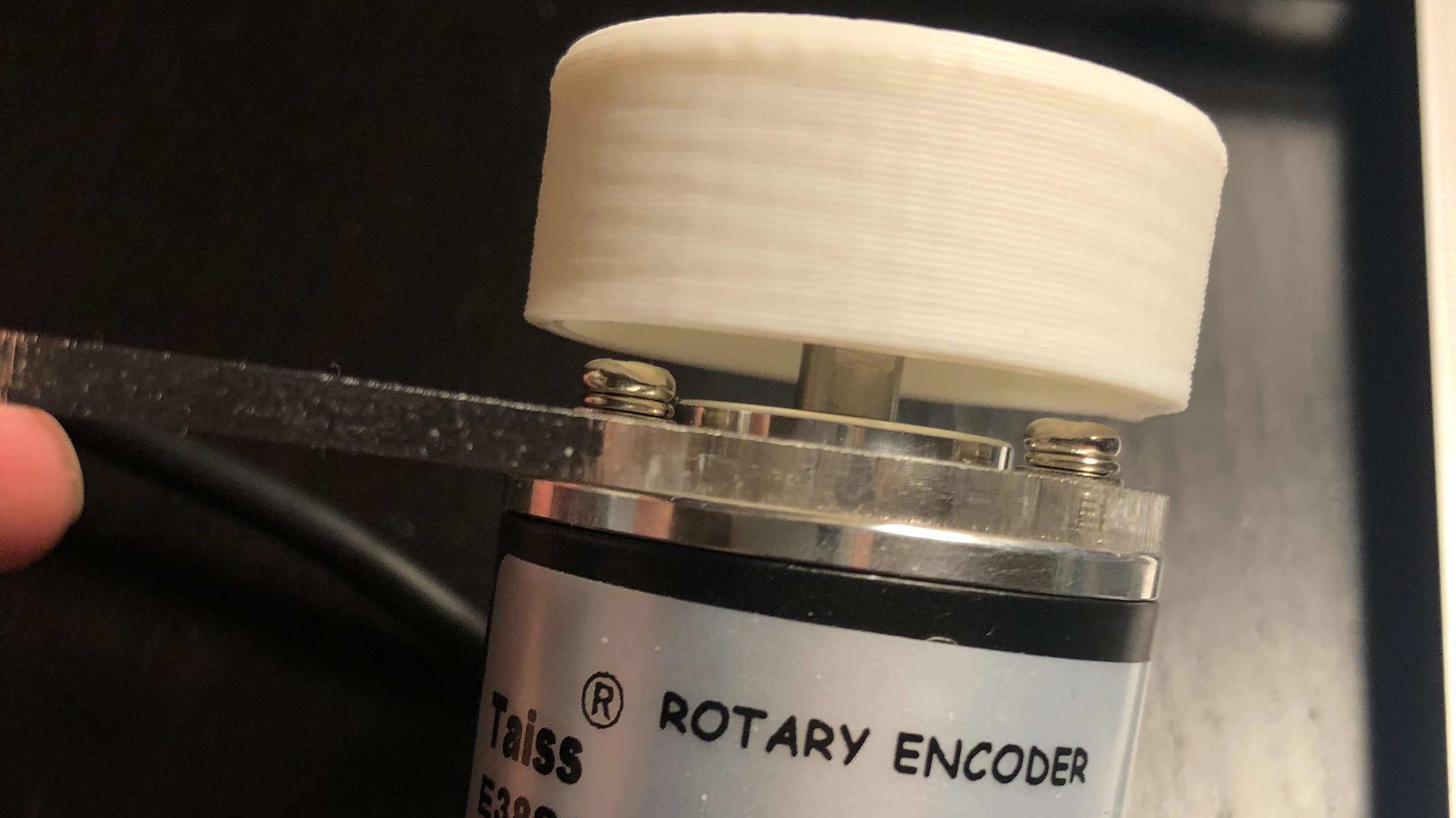
    Printing the Knob
    Glamour Shot for the Encoder – Notice the Comic Sans?

    Next step for the monstrosity, given that I now have two computer-connected knobs side-by-side, is Pong. And then I can return to the original plan of making a camera accessory.

  • Split Flap Display – Part 1

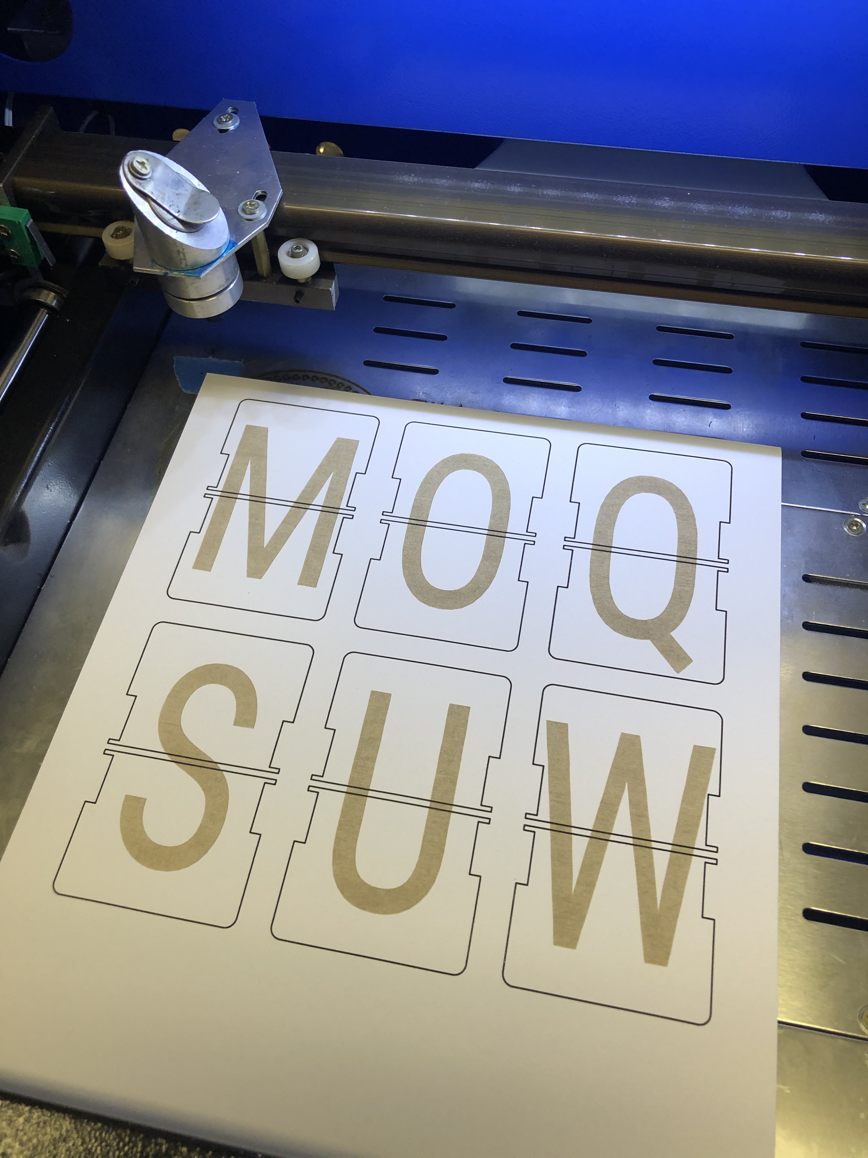
    I recently came by this Technology Connection Video, and I am intrigued by the mechanism of a split flap mechanical clock. I then ran across this GitHub project for a split flap display and I decide to make my own.

    I made one tweak to the design: I made the letters laser engraved and cut out of card stock instead of PVC cards. This includes code changes for generating double-sided SVGs, which made this a lot easier. The PR is here. (now merged)

    The result is actually pretty good.

    There’s a bit of work left to do, but this looks great for a first attempt.