Tag: making

  • Upgrading K40 Cooling System with RGB and Peltier Cooler

    Upgrading K40 Cooling System with RGB and Peltier Cooler

    The K40 laser cutter, if you know about it, comes with absolutely the bare minimum to get you started. Fortunately, it does comes with a cooling solution: You supply your own water bucket, fill it with distilled water, and drop in the supplied water pump. Failure to do that will probably result in a burnt out laser tube.

    As you can probably imagine: this is not a super good system – the system is open-air, and is therefore easy to get contaminated. In my case, my coolant reached questionable consistency (that is, gooey) after a couple of month. So I swapped out the “supply-your-own-bucket” cooling system for a “amazon-cheap-pc-water-cooling” system.

    The system is simple and consisted of 5 parts:

    • a off-the-shelf PC water-cooling pump / reservoir combo
    • a peltier cooler
    • a water-cooling heat-exchanger
    • a CPU cooler
    • a PC power supply

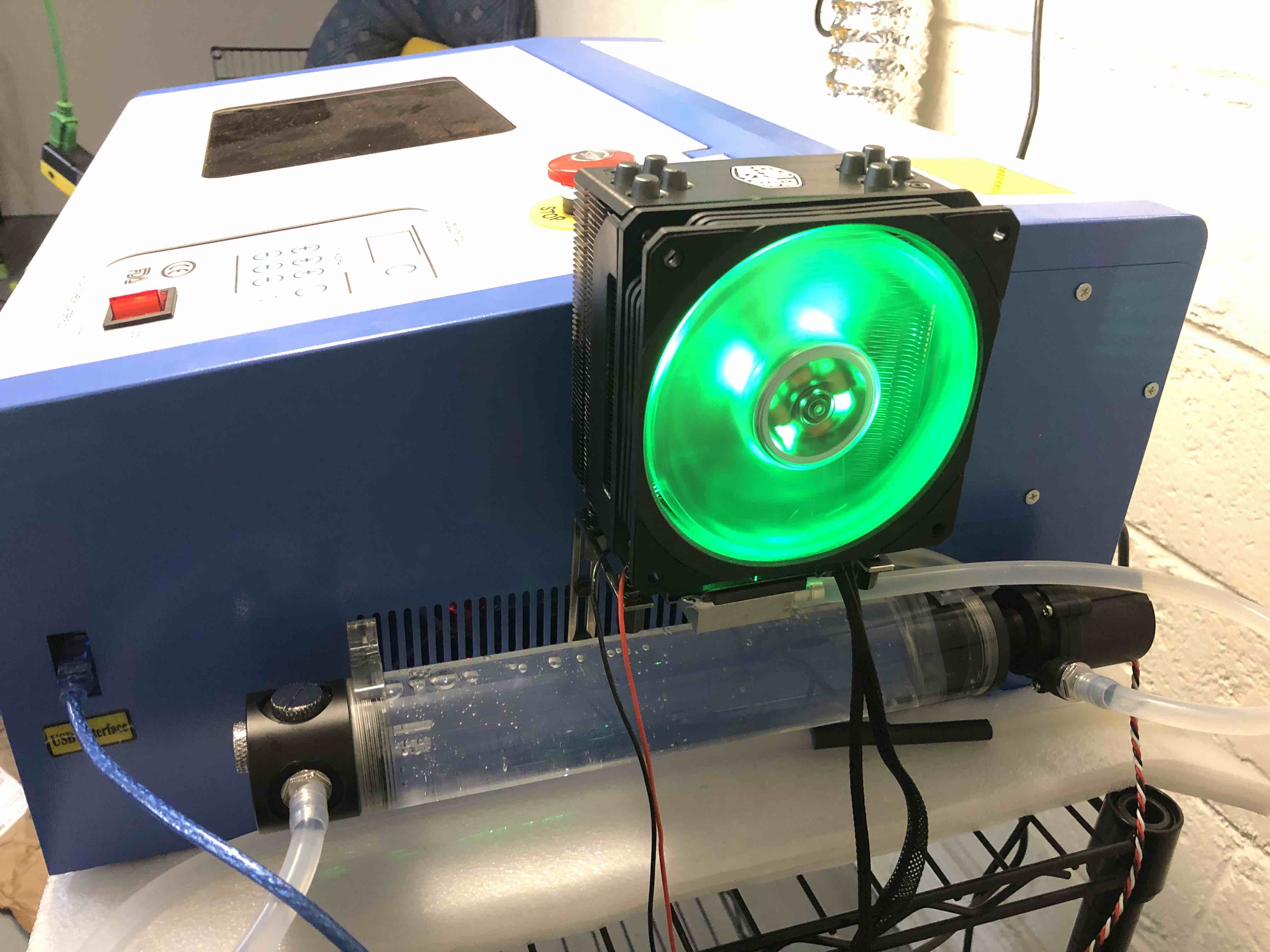
    The pump feeds water into a heat-exchanger, where heat gets extracted by the peltier cooler into the CPU cooler, then into the laser tube and back into the reservoir.

    Everything got mounted on to the side of the machine. It looks reasonably good.

    Laser Cutter with PC cooling parts. And yes, the fan is RGB.

    I hope this results in lower machine maintenance in the future.

  • Etch-A-Sketch Pro – Rotary Encoders as Mouse(s)

    Etch-A-Sketch Pro – Rotary Encoders as Mouse(s)

    I recently got a few of those rotary encoders – I was planning to make them into a follow-focus system. It’s a two part process: 1 – make a USB interface for them; 2 – make software that uses Canon’s EDSDK to interface with my camera.

    So I decided to start on 1, then I got a bit carried away and got this monstrosity made – an Etch-A-Sketch for computers, because everything deserves rotary encoders.

    Etch-A-Sketch Pro in Action

    If you look very closely, each of the encoders has it’s own plug, since each is a independent USB HID device.

    Printing the Knob
    Glamour Shot for the Encoder – Notice the Comic Sans?

    Next step for the monstrosity, given that I now have two computer-connected knobs side-by-side, is Pong. And then I can return to the original plan of making a camera accessory.

  • More CFExpress (CFX) Card Experimentation – PCB Design for a Passive CFExpress – M.2 Adapter

    More CFExpress (CFX) Card Experimentation – PCB Design for a Passive CFExpress – M.2 Adapter

    As I mentioned in a previous post, it seems that it’s totally possible to convert a NVME SSD to a CFExpress Card. So here’s my first take on that.

    Adapter PCB Layout

    J1 is the PCB edge connector for the CFExpress card, J2, J3 are FFC (ribbon cable) connectors, and J4 is the M.2 connector.

    I’m 99% sure that this will not work on the first try. But I think it has a good chance of working after a few iterations. I have sent my gerber files to OSHPark for fabrication, wish me luck.

  • The Mysterious CFexpress Card Specification / Pinout

    The Mysterious CFexpress Card Specification / Pinout

    It seems like CFexpress is going to replace CFast and CF card as the new de-facto DSLR storage medium, at least for Japanese camera manufacturers. The Internet kept its mouth very shut about what this CFexpress Card actually is, with specification no where to be found.

    However, piecing a few separate pieces of information together, we can make up pretty much what the specification is: it’s more-or-less M.2 with non PCI-e pins removed, with a new “INS#” pin. It’s also single sided, and utilizes a PCB edge connector.

    The connector looks like this:

    Here’s the pin assignment table:

    PINSignalI/O DirectionRequired on Media?
    R/O/NC
    Required on Host?
    R/O/NC
    Notes
    1GNDRR
    2PERp1OOR
    3PERn1OOR
    4GNDRRTie to ground if lane 1 present
    5PETn1IOR
    6PETp1IOR
    7ReservedNCR
    8ReservedNCR
    9PERST#IRR
    10+3V3RR
    11CLKREQ#OROActive Low.
    Pull-up of >5kOhm on Host
    12INS#ORRActive Low.
    Tie to ground on media side.
    Pull-up of 100-200kOhm on Host
    13REFCLK-IRR
    14REFCLK+IRR
    15GNDRR
    16PERn0ORR
    17PERp0ORR
    18GNDRR
    19PETn0IRR
    20PETp0IRR
    21GNDRR
    PIN assignment / pinout. Source: http://www.farnell.com/datasheets/2815914.pdf

    Host-side dimensions drawing:

    (From: http://www.rego.com.tw/_admin/upload/product/rego_15562428745ngxni.pdf)

    It seems trivial to make a dummy CFexpress card and just use a NVMe drive instead. Project for another day?

  • DIY $10 Slack Notification Light

    DIY $10 Slack Notification Light

    [youtube https://www.youtube.com/watch?v=BT3PeNsmyPA&w=560&h=315]

    While being isolated at home, my company uses Slack more heavily than ever, and that Slack chime is starting to get old. What if there’s a physical light that can notify me instead?

    I have a Smoko ambient light and a few of Digisparks lying around screaming “use me!”. So I started the project using a combination of these two.

    Digispark
    Smoko Ami Shrimp Sushi Ambient Light

    The circuit is really simple, just a NPN and a resistor. I used a NPN with a beta (use hFE on datasheet for a rough estimate of beta) of 40, and with a 1K resistor the NPN gives about 130mA to the LED. If you want to do this project too, change the R1 value to match your desired LED current.

    Schematics

    I have to make some “battery adapters” to provide power to the light:

    “Battery adapter” made with nickel strips
    Circuitry wrapped in heat-shrink

    On the software side, I don’t really want to reinvent the wheel and build a USB protocol from scratch, so I used code from blink(1) and adapted it for the Digispark.

    The rest is relatively easy: use the blink(1) client and set up a slack integration with IFTTT.

    Code:

    https://github.com/gyf304/usblight

  • Fixing a Clothing Rack during COVID-19 Lock-down

    Fixing a Clothing Rack during COVID-19 Lock-down

    My clothes hanging rack is broken for a bit of time has developed a crack. It’s obviously time to fix it. I already have a piece of aluminum pipe on hand that should serve as a clothes hanging pole. The only problem is that I don’t have the hardware to mount the pole to the wall, at least not easily during the COVID-19 lock-down.

    So, time to home-brew my own solution. First thing would be designing the fastening piece to attach to the wall. I measured the diameter of the pole and the diameter of the screws I have on hand, and designed this in OnShape. (model available here)

    The 3D Rendering of the Mounting Bracket
    Printed

    Works great. A pretty good job given the current circumstances.

  • The Making of the Library Occupancy Estimation System, Part 5 – the Enclosure

    The Making of the Library Occupancy Estimation System, Part 5 – the Enclosure

    It’s almost time to deploy the ESP8266s. I switched from the previous board to wemos mini lite, a smaller board with a variant of ESP8266 (ESP8285). The ESP8285 includes a on-chip 1M EEPROM, reducing the cost. The most important difference is that the newer boards don’t have pre-soldered pin headers. Desoldering pins from the previous board is proven to be tedious and time-consuming.

    While waiting for the boards being shipped from China to me, I designed a enclosure for that board. I can, of course, just stick the boards to walls. But a case is always nice – it makes the project look less cheap (while it actually is pretty cheap).

    The design is consisted of 2 parts: the body and the cap. The body is going to be 3D printed while the cap is going to be cut from clear acrylic panel. 4 M1.5 screws hold the components together.

    The parts are modeled with Autodesk Fusion 360…

    and then made…

    and compared to my sketch…

  • The Making of the Library Occupancy Estimation System, Part 4 – the Frontend

    The only part missing was a front-end. It is 2017, and splitting up front-end and back-end is now a must. This is even more true in this project: serving html and other resources from my free Heroku server does not sound like a good plan – with only 1 web instance, the server can be easily saturated. So the plan was to host the front-end on GitHub.

    The frameworks I chose for this job is Vue for MVVM and MaterializeCSS for the appearance. The reason for using Vue instead of React and Angular was Vue is more suited for small project like this, and is extremely easy to setup (include a js file, add 5 lines of code and Vue is ready). The reason for using MaterializeCSS was simply because it looks nice.

    A few hours later:

    The front-end is pretty bare-bones (< 100 SLOC of js), but it does the job. And thanks to MaterializeCSS, it doesn’t look half bad. The page is also responsive (again, thank you MaterializeCSS).

    The front-end already looks pretty nice on phones, so I took a step further to make it an iOS Web App (no I don’t want to pay $99/year to make it an actual iOS App).

    The first thing to do when developing a mobile app is of course to design an app icon.

    It won’t get me any design award but hey, it’s an icon.

    The tricky part of making the iOS Web App is trying to make it act like a native app. Some CSS magic was used to make it app-like. Also I spend I lot of time working around an iOS bug that made the entire html scroll and bounce even if I told it not to… A few failed attempts later I gave in and used a library called iNoBounce. That worked well.

    How the icon looks on home screen:

    Good enough.

    Frontend Code on GitHub